DashSight - collecting and displaying real time information about your car and your driving

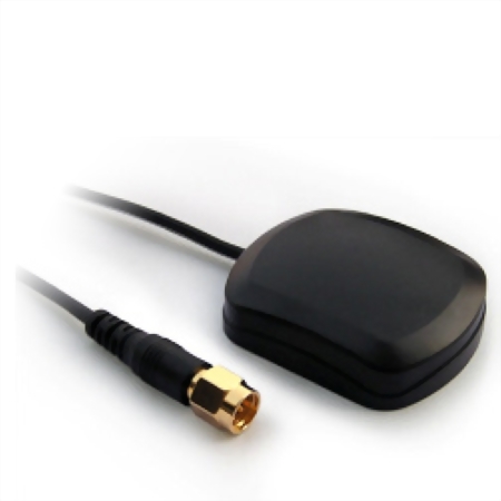
Car enthusiasts can use a GPS enabled device to track their times on race tracks or AutoX courses. These devices are usually standalone and provide high accuracy times based on previously stored map location data. Then can also sometimes interface with the car via the OBDII protocol to get interesting information.

After looking at the current on market devices for tracking cars at competitive events I thought they were over priced. It was hundreds of dollars for a device that used GPS to time how long it took to drive between two points. It was then closer to a thousand dollars if you also wanted to record OBDII data from the car.
I thought that I could do all of this myself. It didn’t seem too hard to run Linux, attach a GPS sensor, OBDII reader and screen and write some code to process/display it all.

I have a background in electrical engineering and work as a software engineer. I have designed PCBs at university so I thought I could figure it all out. I bought some books and started researching.
After starting some basic investigation and research I settled on using a Pine64 board for the CPU and designing my own PCB for GPS and OBDII. I could connect a screen via HDMI and mount it all together in a small package which I could power from the car.

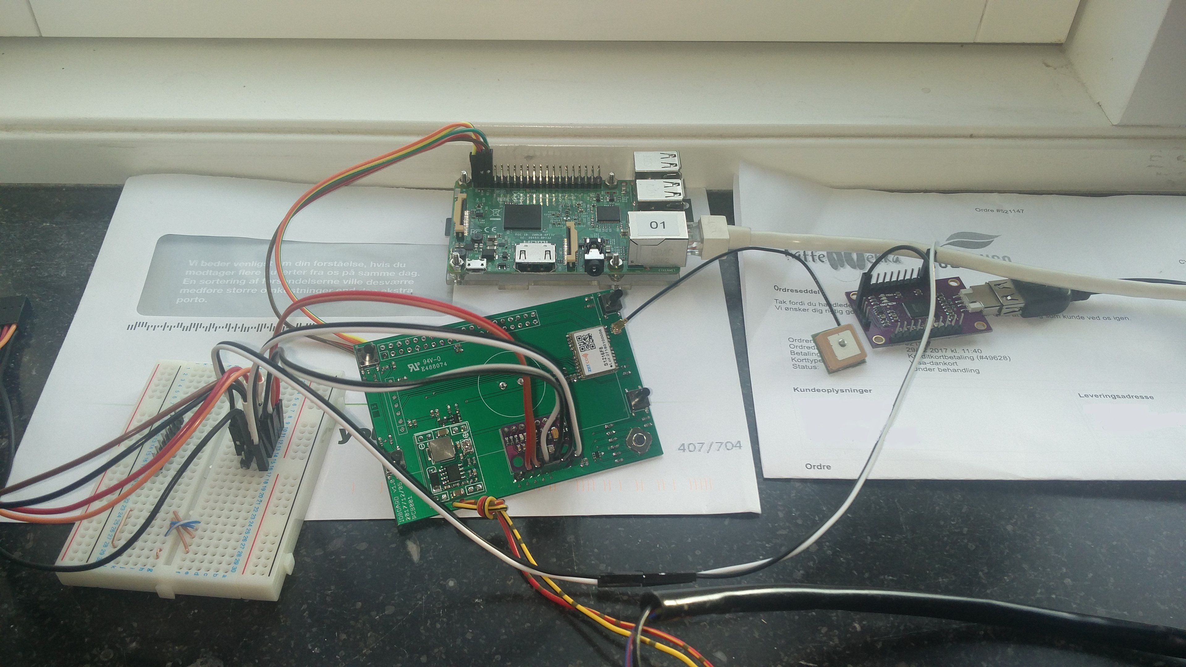
I used SparkFun to get development boards which I could test with then I could implement something similar in my own PCB design.

A long story short, I developed and manufactured a v1 PCB (https://github.com/DashSight/Pine64-Mezzanine-Card) which I debugged with just a voltmeter and reading schematics and datasheets. Unfortunately due to mistakes by me and part availability issues the v1 PCB didn’t really work at all.

I then developed a v2 PCB (https://github.com/DashSight/Pine64-Mezzanine-Card) and had that manufactured by a PCB assembly company. The entire design was done in KiCAD and is open source on GitHub. I also debugged this with just a voltmeter and found a few minor issues. I did speed a lot of time trying to identify what ended up being a bad solder joint.

All while doing this I was building my own Linux distribution (using OpenEmbedded) and writing a program in C with Gtk for the GUI.

Eventually I had something that kind of worked. I had a multi-threaded GUI in C, a HDMI attached monitor with touch support via USB. This was all held together by a 3D printed case I has designed.

Unfortunately it ended up being too big. The HDMI meant it was both too thick and too wide to handle the cable and connection. So I decided to swap to a MIPI DSI attached screen, with an I2C touch controller.

It turns out there was already Linux kernel patches being upstreamed for the Pine64 screen. So I built those and started getting the screen working.

This was a nightmare. I was stuck with no output (as it didn’t work the first time). No worries, I would just get UART going and debug the issue.

What I didn’t know was that UART0 on the board was broken. I was using the other UARTS for GPS, OBDII and WiFi. I wasted hours trying to get UART0 (the default for serial access) working. Eventually I tried using another UART, got that working and debugged the screen issue. I thought I was just not connecting or setting up the UART correctly, but it turned out to be a board issue. At this point I decided I needed a Logic Analyser, as I wasn’t going to go through that pain again.

Now I have a much smaller enclosure, with a LCD attached via MIPI (just like in phones). My PCB provides GPS and OBDII connections. I re-wrote the app in Rust, so I have a Gtk gui that the user interfaces with (https://github.com/DashSight/DashSight).

Next I thought it would be cool to have an accelerometer. I bought an accelerometer online form SparkFun to test before extending my PCB. I connected it all up and nothing worked. No worries, now I have a Saleae Logic Analyser (https://www.saleae.com).

With the help of the LA, I could figure out that nothing from the I2C bus was happening. I debugged this to a bug in my kernel device tree. After fixing that I could see data on the bus, but it still wasn’t working. Using the LA’s I2C decoding I could see the packet going to an address, but no response. After checking the data sheet I realised I had to ground the selection pin to have the slave accelerometer work at that address, after fixing that and connecting the !CS pin I had the accelerometer connecting and working!

In this case the LA didn’t offer anything I wouldn’t have figured out eventually. It just reduced the time spent debugging something as I could see exactly what was going on.

After awhile though the I2C bus would stop working. Using the LA with the analogue input I could see that even though I had the I2C master set to pull-up the line it wasn’t enough. I saw very curved waveforms when the bus transitioned from low to high.

I realised that even though I had it working with the I2C master pulling up the line, it wasn’t strong enough. So I added some pull-up resistors to the I2C bus and the LA showed a much better result.

This issue is something that I don’t think I would have figured out (at least not for certain) without the Saleae Logic Analyser. It worked most of the time that it would have been a nightmare to debug the real issue. The analogue view from the LA was incredibly useful.

I’m still actively working on the project, adding new features such as temperature reading and an IMU. After spending a fair bit of time I have realised why the current options are so expensive. There is a large amount of work required just to get accurate GPS data, yet alone all of the other work.

4 Likes

This is fantastic! Interesting note on the slow rise times. Great you were able to catch that and solve it with the stronger pullups.

Nice project, Alistair! I’ve been working on a similar hobby project, but for motorcycles. I designed a HAT-like PCB “ioboard” for a Raspberry Pi 3B (using Eagle 7) with a screen (2.42" OLED), 5 buttons (4 simple + a 5-way “joystick” button), 12V DC-DC converter to 5V (MP1584 module) to power the system from the 12V power on the bike, a 50Hz GNSS (SkyTrax S1216F8) receiver, 10-DOF accell/gyro/magnetometer/barometer (MPU9520+BMP280).

I had the board manufactured by pcbway in China - very good quality, but I deliberate kept myself within the conservative design rules to meet their $5/10pcs target. By mistake, I ordered them not to put solder mask over the vias, which they dutifully didn’t do. The only mistake I found on that board was that I connected the GPS module’s UART I2C interface to the 10DOF module and on to the RPi. It turned out that when I was communicating too much on the I2C bus, the GNSS would crap out and pull down the I2C data line. Two quick cuts to the I2C lines put the GNSS module out of it’s missery (and restored the health of the I2C bus).

I have the screen initialized and can printf() characters to it, as well as talk to the 10DOF and get reasonable data from the accellerometer, gyro, and the altimeter. I haven’t tried to get in contact with the magnetometer yet. The RPi have proved a pretty good bootstrapping environment, although it is way overkill for my eventual target. All the way through this, the LogicPro 16 has been extremely useful.

I am currently looking to retarget the design to use an ESP32 processor, which should be a better match for lower-power. Since the OLED screen is pretty expensive, I am looking to retarget the HMI to a touch-sensitive TFT screen instead (there are open-source drivers for ESP32 available). This should also reduce the pin-count pressure. One challenge that remains is how to deal with the GNSS: on the RPi I can just use gpsd, but since the ESP32’s FreeRITOS isn’t a POSIX-compliant environment, porting is not straight forward (or even pointless).

Cool!

I decided to go with a large screen 7" and touch screen to avoid dealing with button and joystick inputs. It does make the whole thing very large though, so probably wouldn’t work on a bike. Actually it’s pretty hard to mount on a car as well, with the large battery pack it’s pretty heavy.
50Hz GNNS receiver is quick! My current one does 10Hz max, but I’m upgrading to a u-Blox that can do 25Hz. I’m also working on adding an IMU to get acceleration and gyro measurements. So far OBDII and GPS are using UART so the IMU and temperature sensors will be the first things on I2C.

I will look at pcbway, I used SeeedStudio for PCB fab and assembly but haven’t had great results, although they are pretty cheap.

My plan is to power the board from the OBDII as well, so I’m not really concerned with power, as long as it’s below 1-2A (USB range) then I’ll be happy.

I’m using gpsd as well, it’s really useful. I’m also using Gtk for the GUI and libchamplain for the maps so I’m set on a Linux environment. It ends up being overkill, but it simplifies everything. I don’t have to worry about handling displays, maps or device drivers.

You could probably just parse the NMEA sentences manually if you aren’t sharing the GPS data with multiple programs.

Something that would be really cool is a generic way to do IMU data, like GPSD but for accellerometer and gyro. If you have anything you can share that would be great.

Alistair,

Yeah 50Hz sounds really cool until you realize that the high update rates comes with a few drawbacks: it’s much more sensitive to random reflections and obscurement (e.g. driving under a bridge), and you may not get a real practical improvement in accuracy.

What I’ve found is that my old Starlane Stealth GPS-2 (with a 5 Hz update rate) and PZ Racing’s Start Next (with a 50Hz update rate) yield identical laptimes down to 10msec resolution, if both have good reception. The Starlane laptimer seem to have a much better (and active) antenna than the PZRacing laptimer: the Starlane doesn’t give a hoot about it’s orientation, whereas the PZRacing will have a huge 2D error if not oriented with the antenna pointing straight up towards the sky.

I recently purchased a U-Blox NEO-M9N breakout module for testing (I presume it’s the one you are looking at), and with the u-Center software it quite good at visualizing just how important a good antenna is to get good accuracy. The small 15x15mm ceramic patch antennas are nice (like this), but an external active antenna, possibly magnetic (this) gives a major boost in performance.

If you haven’t noticed already, make sure to connect the GNSS module using a direct UART port along with the PPS signal to synchronize the timing with. For me, making sure that the IMU data and other data (main axle rpm, crank rpm, throttle position, suspension position etc) are timestamped & logged together with the right GNSS position is important for data analysis later.

Here’s the board (modules and all components hand-soldered under a microscope:

and test setup in the window sill:

For integration of IMU and GPS data, look for RTKlib or something similar. I haven’t gotten to that point yet, but let’s swap notes.

I had issues with a 1Hz update rate jumping around as well. I think the antenna design on my PCB was sub-optimal and was picking up too much noise from other ICs. Even though I’m using an active antenna there is still a lot required to get the PCB trace right. I did lots of testing trying to remove noise sources from the GNSS module. It ended up working pretty well when the expansion board was away (with jumper cables) from the CPU board. When stacking the boards there was too much noise from the CPU components.

PS: If you are driving around under things, ublox also has dead reckoning chips that might help with that.

Yep, I’m swapping over to the NEO-M9N. I have designed a new schematic and PCB with the NEO-M9N. Hopefully between the better IC and an improved design I can get a more accurate and reliable position.

Yep, I’m using direct UART for the GNSS. I’m not using the PPS, do you find it useful? I was planning on just using the system time for my timestamps.

Wow! That’s some impressive hand soldering skills!

I have some basic IMU values working. I ended up using libiio (there is a Rust binding library) to get the values from the Linux kernel.

I made a very short antenna stub to the u.FL connector, to avoid antenna mismatches. I only have a 2-layer PCB, buyt I put the GNSS module in the corner to have as little interference from the other components as possible. Good antenna design/matching is critical to get good performance from the GNSS receiver. The good news is that the NEO-M9N is really good at picking up birds (I’ve seen more than 30 simultaneous satellites).

U-blox’ dead-reckoning chips (thr RTK ones) are horrendously expensive.

Using the PPS signal gets you within a few nsec of the top-of-the-second, whereas all bets are off on the UART sentences. Here’'s a quick snapshot I made to illustrate the problem:


As you can see here, there are more than 18.7 milliseconds from the assertion of the PPS signal until the the u-blox even starts transmitting the sentence. Now add to that the latency from sending & receiving the sentence (just over 6msec at 115.200baud) and then add the latency added by the receiving UART and from the interrupt until you timestamp the sentence.
I think you’d be hard pressed to get below a 25-30msec delay.

If you use the rising edge of the PPS, you should be able to use that to feed into your timestamping timer. If you want to be ready advanced, keep track of the various timestamps so you use this to correct the frequency of your timer (DLL in essence). This is what the time-nuts do with NTP to get sub-100nsec error for their setups.

Edit: I misread 18.7msec for 187msec. Fixed.

I thought there are dead reckoning chips that aren’t RTK, so aren’t crazy expensive.

Thanks for the advice.

I have now added a PPS for my next version, so hopefully that will give me more accurate timing information.

I have now updated my design to use the u-blox NEO-M9N (still with an active antenna), an IMU (via I2C) and I even expose some I2C connectors (via Qwiic) to add extra features in the future. I’m hoping to connect some temperature sensors via I2C and see what I can measure with that.

I converted a lot of through hole parts to SMD so I squashed down the size. I have heaps of spare space on my board now, so I can think of even more things to add (or maybe gen 4 I’ll just shrink the board).