Hello,
I have probes connected to UART Tx and Rx line. I have same settings for both instances. I see framing errors on One line while other looks ok and data makes sense. Is there any additional setting that I have to do apart from below.
Please support.
Thanks!
Hello,
Thanks for posting, and sorry for the trouble with this!
A framing error indicates that the serial decoder found a binary 0 when it was expecting a binary 1 stop bit.
The software highlights this with markers if you zoom in a bit.
Here is what a successfully decoded byte looks like:
The decoder adds white dots in the center of the 8 bit fields for the data bits. (It does not normally mark the start or stop bit)
If those white dots don’t appear well centered in each bit field, that could indicate a problem:
- The actual baud rate might not match the baud rate setting you selected.
- You might be using the wrong IO voltage standard. This can cause high and low bits to have different widths. (Generally not that big of an issue, but this would matter more at 4MBaud.)
- There could be some sort of signal integrity issue. 4 MBaud is pretty quick for serial, so signal integrity issues that wouldn’t normally be a problem at lower speeds could cause problems here.
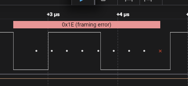
Here is an example of a framing error caused by using the wrong baud rate.
When a framing error is found, the decoder places a red X where the stop bit should be. Stop bits should 1, but in this case the signal is still low.
You can also see that the write dots are pretty close to those two edges in the middle of the byte. That’s also a clue that the baud rate isn’t right. In a cleanly recorded serial capture with the correct baud rate set, transitions should be centered in the gap between those dots.
In this example, the baud rate in the analyzer settings is set higher than the actual baud rate of the signal. Reducing the baud rate in the analyzer settings could fix this.
Feel free to post a zoomed in screenshot, or even a copy of the capture. We’d be happy to take a closer look!
Hi,
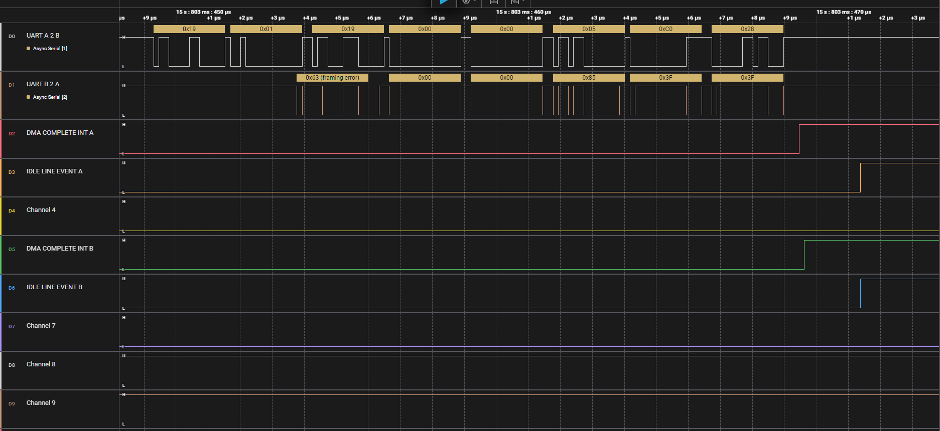
Thanks for the explanation. When I use a different tool, I see no issues with the decoding part. Moreover, “Uart A2B” looks ok with Saleae. Issue is with “Uart B2A”
The recording looks pretty different in that other tool.
In our tool, B2A starts about 2 bytes after A2B, and both channels stop at the same time. In the other tool, there seems to be a small offset between A2B and B2A, but that’s about it. Is that normal operation for the devices you’re recording?
To debug this further, Please save a copy of that capture and send it to is. You can save a capture from the File menu > Save Capture.
I think you can attach it here, or you can send it in to support: https://contact.saleae.com/hc/en-us/requests/new
Once we have a copy of the capture we can take a closer look.
Hi,
Yes, that is fine. I am more concerned about decoding. Start of B2A 2 bytes after, is not expected if they stop at the same time. Attached is the capture recording.
Session 1.sal (1.2 MB)
I swapped the probes, and now B 2 A data makes sense. Same software is running on embedded device. That means, there is correct data on the bus, but something is wrong when decoded or some setting is missed.
1 Like
Ah, I see the problem. You need to increase the device sample rate.
You’re sampling at 6.25 MS/s, but the serial signal is running at 4MBaud.
We recommend sampling at a minimum of 4 times faster than the signal you’re recording, and in general sample significantly faster, to improve timing resolution.
To raise the sample rate, just open the sidebar to the device settings panel, and select a higher rate in the drop down.
I would recommend 100 MS/s. This has a good balance of high timing resolution while avoiding high CPU load required to handle higher sample rates.
1 Like
Hi,
Looks like the problem was with voltage setting, when I make 3.3 volts, it decodes correctly. I also changed to recommended sampling rate.
Thanks for your help!