Hello, we purchased this logic pro 16 intending to log the value of an 8 bit microcontroller port over time. A new value is written to the port when the state changes.
I assumed that either we can group the digital lanes into a bus, or else use the parallel decode option. However I see no capability to display a bus and the parallel decode option requires a clock.
This is a rudimentary logic analyzer function. Is there an option hiding somewhere?
Hey @keegan, thanks for letting us know your need for this. Unfortunately (and quite bit surprisingly), we don’t have a way of decoding this simple case.
Currently, our pre-installed analyzers will decode messages via the following methods:
via a clock signal
via a asynchronous signal (no clock) using a specified baud rate
What’s missing is a way to decode messages upon digital channel transitions.
Okay, thanks for letting me know. For now we will implement manually by exporting raw data.
Normally on devices I’ve used you can just group bits into a bus on the display. Implemented as an analyzer in your software, I think you could simply make a different parallel mode that is sensitive to rising/falling edges on all data bits.
Understood. Also, thanks for finding the already existing idea post. I missed it when doing a quick search of existing ideas. I merged all comments into that one now so we have one place to track all the votes and notes from everyone on this feature request. https://ideas.saleae.com/b/feature-requests/bus-display/
We are also capturing data from an 8-bit port.
For us, a useful feature would be logical operators on the trigger. In our case, trigger on nWR (not write) OR nOE (not output enable). So an OR of 2 channels would be good.
Another feature that would be good is to allow channels to be grouped, i.e. instead of seeing 8 separate channels we see one bus showing HEX data. The same way some simulation software can display it.
@techtest Thanks for letting us know! For your first idea:
For us, a useful feature would be logical operators on the trigger. In our case, trigger on nWR (not write) OR nOE (not output enable). So an OR of 2 channels would be good.
I added a comment and vote for you in the feature request post below so we can track your need for this:
I’m curious to know more about your second idea:
Another feature that would be good is to allow channels to be grouped, i.e. instead of seeing 8 separate channels we see one bus showing HEX data. The same way some simulation software can display it.
Can you describe what kind of signal you are working with? Feel free the attach a .sal capture file as well. Could our simple parallel analyzer solve this for you?
It is more of an idea for the graphic display. I have tried to load an example jpeg of what I mean (this particular screen shot is from Modelsim).
We have 4 Saleaes and are very happy with them…normally we just use them for I2C, SPI, UART or a few discrete signals.
I have actually switched to a DSO that has 16 logic channels for the moment.
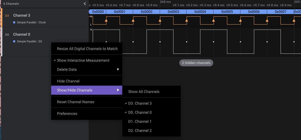
@techtest To get something similar, you can collapse channels that you want to hide from view like in the image below (using Simple Parallel analyzer as the example).
This will essentially leave you with a single track (the clock channel that contains the decoded data). You can do this for multiple instances of the Simple Parallel Analyzer (i.e. view multiple bits of data within a single track).