I’m trying to read the data from a CC1101 chip. I have the SPI data currently. I used the Salae_CC1101 decoder, which gave me the register setting, extremely helpful. The configuration for the CC1101 is putting into Async Serial mode which changes the GDO0 pin to “data” and sets the GDO2 pin as the clock.
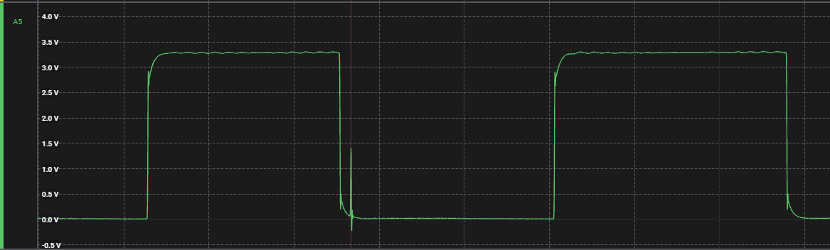
I can see data coming back on the GDO0 pin (see attached capture) but I’m having difficulty configuring either the Async Serial or Simple Parallel analyzers. To be honest, I’m not really sure which one will fit my purposes. The SP has a clock and data “configuration” but the data coming back is all 0’s.
I’d appreciate any guidance to get me on track to decode the raw RF data coming back on the GDO0 pin.
Out of curiosity, I took a quick peek at your capature file. It looks like it is putting the packet format (PKTCTRL0.PKT_FORMAT[1:0]) into 3 (11): Asynchronous serial mode and setting IOCFG2.GDO2_CFG[5:0] to (0x0D) Serial Data Output. In asynchronous output, I think the GDO2 pin is the ‘raw demodulated’ signal, where the serial encoding scheme depends on the RF transmitter. What is transmitting the data you’re trying to decode?
Depending on the transmitter/receiver you’re trying to decode, it may be better to use the Manchester or Async Serial analyzer to decode it. It may also be handy to use the Glitch filter on the serial output channel to remove the possible noise pulses that may occur in the raw RF demodulated signal.
Otherwise, you could use the Simple Parallel Analyzer along with your own high-level analyzer to create a custom decoder in python, or write your own low-level analyzer using the Saleae Analyzer SDK. However, this is a more advanced method vs. being able to use the built-in analyzers and/or finding a suitable 3rd party analyzer, if available.
Finally, it looks like there are two CC1101 high-level analyzers listed in the Logic extensions:
… and it looks like the first may have a bit better higher-level decoding that may be more helpful for reverse-engineering your CC1101 settings, as it seems like you can search the data table for registers and more easily see the values being written.
The next step requires more detailed analysis of the CC1101 settings, and/or more knowledge about the specific RF protocol(s) and device(s) that are being monitored – to help figure out which asynchronous serial protocol to expect, and what analyzer(s) would best help you to decode your serial output data.
Thank you BitBob for taking the time to look over my capture. I’m trying to decode the signals sent by an Autel MX-1 programmable TPMS sensor. The capture is from an Autel MaxiTPMS, TS508 tool. I connected the logic analyzer to the SPI pins of the CC1101. I thought having the configuration they were setting the CC1101 to would help me to understand how to decode the messages coming from the MX-1 sensor. Since I posted this question, I’ve done further testing and it appears that most, if not all of the different vehicles use the same CC1101 settings. I believe what is happening is, they are setting the CC1101 to receive the message from the MX-1 in serial mode and depending on which vehicle is selected, they use internal firmware to correctly parse out the data into something meaningful.
I think you are correct though and I’ve been trying to decode the wrong signal. After looking at the capture again, I was misinterpreting the data, the GDO2 line, which I initially thought was a clock signal does in fact look like the raw data coming out of the CC1101.
I’ve since been trying different decoders, async serial, manchester, etc to try and get the 0’s and 1’s to possibly pass onto some RF decoder to try and find the Hex(ID) of the TPMS sensor that the TS508 reads, in this case, 60AD7489. Haven’t had much luck thus far but I’ll keep trying :).
Again, thank you for your assistance, it’s greatly appreciated!
Did you capture data after the sensor was already programmed, or was it still new? If so, what vehicle make/model/year was it programmed for?
There is a whole ecosystem for RF based hacking known as Software Defined Radio (SDR), and an open source tool rtl_433 that has a lot of different TPMS sensors (and other wireless devices) supported:
… and device encoding schemes:
For a general overview on rtl_433, see:
As far as your capture, I think one channel is indicating signal strength, while the other is the async serial data. The CC1101 is doing the RF demodulation that may be using:
… and the just de-modulated pulses come out the async serial line.
These de-modulated signals/pulses may be:
Manchester encoded bits
Pulse-Width modulated (PWM) bits
Pulse-Code modulated (PCM) bits
or other bit-encoding scheme
However, the de-modulation could be noisy, and have false edges (noise pulses) in the digital output. If so, it may prevent any of the built-in decoders from working properly, as most decoders aren’t very noise tolerant. That would require you to use the software glitch filter (linked above) to ignore & filter out any pulses that are too short.
The main triq.org site has a lot of additional useful tools for helping to reverse engineer RF encoded data, and you can also look at the rtl_433 github site for more hints on how to analyze RF signals. Knowing the bit-level encoding scheme is critical to figuring out you logic setup & analyzer settings.
That’s actually where I started this whole process. Catching RF signals out of the air with my RTL-SDR was a little daunting with all the variances that can make my head explode, LOL. My thinking was that if I could get what the CC1101 was pulling out of the air, I’d have a better shot at trying to figure this stuff out. It appears that there truly is no easy way for this.
I have the Autel tool that can program the TPMS sensors and I have a cheat test rig (old tire balancer) that I’ve been using to spin the wheel to try and get “real world” information from the TPMS sensor. I’ve also started using Universal Radio Hacker to try and make sense of it as well. The capture that I posted here is from an X7 BMW which the rtl_433 guys have figured out a couple of the generations of the BMW sensors but what I’ve found is, this must be another newer generation at least from what I’ve seen from the preamble, but I’m so new at this, I don’t even know if the preamble I think I’m getting is actually the preamble.
I can honestly say, this whole process is maddening, LOL. I’ll keep plugging away though and I really do appreciate your time helping a newbie and giving me new ideas and thought processes to build upon.
Okay, I’m guessing this thread might be from those earlier attempts:
My understanding is that your CC1101 trace (async serial output) should be the same as your rtl_433 demodulated output (i.e., the pulse waveform in I/Q Spectrogram & Pulsedata should match your Saleae digital capture for the same RF input).
That being said, the attached *.cu8 files from post above look a lot cleaner than your *.sal file attached above. Have you looked at the analog vs. digital version of the channel to make sure your logic levels are correct? Also, you might want to capture both rtl_433 and CC1101 async serial output on the same test case to confirm both instruments are seeing the same ‘digital’ trace.
Finally, the picture showed this was a BMW X3 E83 (2003 - 2011) at 433 MHz? Was (is) rtl_433 unable to decode this TPMS format natively? E.g., -R 0 and -R 252 (BMW Gen4/5 TPMS) or -R 257 (BMW Gen3 TPMS)? It looks like recent activity may have added Gen2 support on Gen3 recently, per:
… so it might work now?
Btw: do you have a certain end game in mind? Are you making your own TPMS decoder for this sensor, with CC1101 chipset? Just hacking/learning, or .. ?
[Edit]
Looks like Gen2/3 use the following settings: rtl_433 -Y autolevel -Y minmax -X "n=BMW_G3,m=FSK_PCM,s=52,l=52,r=1000,preamble=cccd,decode_dm,bits>=190"
… but see comments in source file linked above for more details (RF modulation and bit encoding schemes, etc.)
That’s correct, that’s the thread I started when trying to understand what was happening, and all this time later, I don’t feel as I’ve made much progress. After going over your response last night I redownloaded the rtl_433 and tried to get the sensor to activate but didn’t have any luck and I’m unsure if it’s the sensor isn’t sending out the correct pulses or if the existing bmw solutions aren’t working with this particular model. I’m currently just activating the sensor using the Autel TPMS Programming Tool (TS508).
I created a custom automotive air-bag management solution for trucks, and my particular truck is older without TPMS capabilities, naively, I added the CC1101 to my design in hopes I could figure out how to capture the RF signals. My goal was to support an aftermarket Autel MX-1 TPMS sensor that people could program for a Chevy, Ford, Ram, etc. The BMW implementation was just so I could throw the device in the car, drive around and make sure everything is working correctly.
As you saw from the original attempt catching the RF signals out of the air, not making much headway, even with the assistance of some really smart people. I switched tactics and started attacking it from the receiver side and haven’t had much luck with that approach either. It is a good idea though to try and match up the CC1101 capture with the raw RF capture and at least get a baseline of matching captures, because like you pointed out, they should realistically be the same. I tried running the Universal Radio Hacker captures through AI and it actually figured out the preamble and the HEX ID but after rerunning the capture, it completely changed, which leads me to believe there is a flaw in my capture process. The other roadblock at this point is configuring the CC1101 to actually receive the signal. I have a dev board connected to SmartRF Studio as well as my air-bag controller custom hardware, and it never sees a signal, it’s probably one bit not configured correctly causing it to never capture any data.
I’m going to see if I can the CC1101 and RF captures to match consistently, that way I’m not just stumbling around in the dark.
Thank you again for spending your time helping me out with this!
I programmed my TPMS sensor to match the, BMW X3 E83 (2003 - 2011) at 433 MHz and ran the rtl_433 command, -Y autolevel -Y minmax -X “n=BMW_G3,m=FSK_PCM,s=52,l=52,r=1000,preamble=cccd,decode_dm,bits>=190” and when I triggered the sensor, I actually received data. That was exciting so I reprogrammed the TPMS sensor to the BMW X7 and restarted rtl_433 using the same command and received the following results:
That’s the furthest I’ve gotten in years! Now, I’d like to recapture the CC1101 GDO2 data and see if I can use rtl_433 to decode it to see if it all matches up.
The reason for continuing is I don’t believe that rtl_433 has any RAM captures, if I can figure it out, maybe I can contribute to the project. I’m pretty sure they have Ford already done. I’ll have to see if a Chevy exists also. I really only need the 4 for now.
This is pretty exciting, thanks again, your thoughts and contributions have moved this exponentially for me.
I think the GDO0 is an indicator of signal strength, and GDO2 would be ‘valid’ only when GDO0 goes high (enough signal detected). That being said, the previous captures didn’t have very good signal quality on the GDO2 channel – lots of short pulses.
Things to check:
Good ground connection for Saleae logic?
Confirm analog voltage levels vs. digital thresholds?
Hardware circuit / noise immunity?
(If you are designing circuit/layout)
It does support a variety of TPMS sensors, including a few Schrader TPMS (who supplies at least some mopar parts). There is a big variety of suppliers, protocols, and encoding schemes – so your specific vehicle may not be supported, even if an earlier/later model year (or country variant) is. E.g., some use 315 MHz in one country and 433 MHz in another, as local regulations do/don’t allow certain frequencies for TPMS usage.
Btw: what does an “airbag management” system do? Is this for crash protection, or some other type of airbag? Wasn’t sure how that related to TPMS, so curious about the end product.
I’m currently trying to get good signals so that Logic 2 can decode them for me. It has been a challenge to get a clean capture, which is odd because the RF capture is way cleaner. I’ve verified the ground is good but I think I’m running into Bodge wires attached to the Saleae. I’m working on it though :).
My hardware is designed to manage the rear ride height of pickup trucks. When payload is placed in the bed, it recognizes the change in height and switches on the compressor for the rear axle air bags until it’s back to “level”. I thought adding TPMS would be a nice addition to the board but quickly becoming a situation of diminishing returns. I’m like a dog with a bone so I’ll keep at it to add the decoders that rtl_433 doesn’t have yet.
Thanks again for your help, having a second set of eyes with more knowledge than myself is greatly appreciated.
I would definitely take advantage of Saleae’s analog capabilities and confirm how the underlying signal looks. Are the short/noise pulses in the digital signal actually coming out of the CC1101, or are they glitches in the wiring/capture instrumentation? I’d suggest using the highest analog resolution (50 MS/s) on just GDO2, and confirm what it’s doing during the short pulses. Is it tracking the digital waveform rail to rail (0V to VDD), or is the voltage just dipping slightly around the digital threshold w/o going all the way to the rails?
If the analog looks clean, then it may be something in the CC1101 settings. The Autel firmware could be handling the noise by software glitch filtering or other digital sampling strategy. Does the Autel tool decode it okay while the Saleae is connected? The rtl_433 and SDR setup can do a lot of automatic clean-up in the RF/analog domain (auto gain control, etc.) to provide a cleaner digital demodulated / digitized signal.
The CC1101 should also have settings to better ‘tune’ the RF signal & improve the quality of GDO2 output, but the Autel’s firmware should be handling that. Maybe they just try to clean it up in software vs. optimize the CC1101 settings?
I took a new capture, changing Channel 5 (GDO2) to Analog (50 MS/s). It does look really different than capturing it as a digital signal. I tried to apply Simple Parallel and I’m not sure it supports analog captures.
The VDD is 3v3 on the Autel tool, which looks like it’s the same in the analog capture. Not exactly sure how to analyze the analog channel at this point. Any insight would be greatly appreciated. I’m thinking that if I can interpret the GDO2 analog line to 0’s and 1’s I can possibly compare that to the raw RF capture.
To do this comparison, you actually want to capture both analog and digital – to see where the glitches are, and how the analog looks near those glitches.
Given that VDD = 3.3V, you want to use the 3.3+ Volts digital threshold (which you already are). Looking at the analog data (without digital to compare) – it does look like the signal has some noise in it, such as at 54.756672 ms:
No, the analyzers can only be applied to digital channels, not analog. That’s another reason to capture both analog + digital on the same channel and one of the nice features of the Saleae logic – it allows you to to capture both to help debug scenarios like this (vs. having digital only).
The analog view of GDO2 is still the same asynchronous serial output – which is supposed to be a digital pulse signal, and should compare to the demodulated RF output from the capture using an SDR and rtl_433 (which is also ‘digitizing’ the RF modulated signal). Thus, having all of the following:
A Saleae capture (*.sal file) that includes:
GDO2 (both analog + digital)
(capture rate of 50 MS/s analog, and max allowed digital (250 MS/s?))
All the SPI bus data (to see how CC1101 is configured)
Digital threshold is set to 3.3+ Volts (given VDD = 3.3V)
An rtl_433 capture of the same RF transmission (in *.cu8 format, I think)
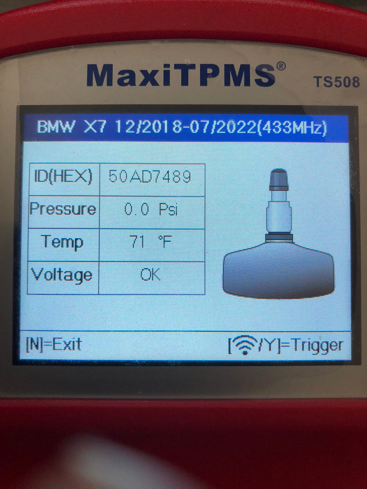
A snapshot of the Autel tool’s screen showing the decoded output
(to confirm the Autel’s decoded pressure, temperature, and sensor ID, etc.)
… should help to better figure things out with your setup.
Is this still the same TPMS sensor, which is still configured for BMW like before?
That’s VERY interesting, learning so much! You’re absolutely correct! The noise that is on the analog channel is definitely causing, I guess it would be called false positives? I reuploaded the Saleae capture to the one drive link. Attached here is also the picture of what the Autel tool received while triggering the Saleae capture.
I have to get my SDR setup and I’ll add the .cue8 file to the one drive directory as well when I pull it out of the air.
Yes, the capture is from the BMW X7 capture and using the same Autel MX-1 TPMS sensor.
Yes, the glitch you see in the analog channel is corresponding to a pulse in the digital channel, which will mess up any attempt to use the digital analyzers as most are not very noise tolerant and expect the digital pulses to all be ‘real’ (i.e., want to have a clean capture).
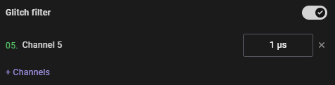
That being said, you can use the software glitch filtering feature:
… and pick a value that is large enough to filter out any such noise glitches. It helps to know what the minimum pulse width is in a ‘good’ signal, and then pick something that is reasonably smaller than that (e.g., you could use something like ~1/2 the shortest expected pulse or less for a lighter filter, up to something ~90% of the shortest pulse for a heavier filter). It is still better to clean up the source, but it is nice to have the glitch filter to still extract an analyzable signal from the noise.
Note: on the new capture, I didn’t see any activity on channel 4 (GDO0 ?), which I thought would go high (1) when the signal was considered ‘strong enough’ by the CC1101, but it stayed low the entire capture?
Good catch! Two of my bodge wires were touching, and it messed up the capture, sorry about that. New capture is out on the one drive, the 1us Glitch filter cleaned it right up, it appears I now have a “clean” digital signal that matches the analog signal!
Next step is to apply an analyzer to the digital GDO2 channel?
I still think you should get a waveform that matches between Saleae capture of the CC1101 output and the rtl_433 demodulated pulses, as I think they should be the same if recorded for the exact same event. Now that your digital capture is clean, I think you can turn off analog channel and maximize your recording length – just to make sure you aren’t capturing some other 433 MHz data besides the one desired.
There might also be a low frequency RF output on the Autel unit used to ‘wake’ the TPMS sensor that you might want to capture (if interested), but not needed if you’re only interested in receive/decoding a sensor that is awakened by other sources (i.e., vehicle/wheel motion or other tools).
The confusing part is that your rtl_433 captured pulses are ~52 us minimum, while your CC1101 pulses with logic appear shorter than that. Either they’re not the same event, or maybe CC1101 is demodulating / decoding differently than rtl_433? This is where URH might help (if they’re same event, but coded differently)?
Until you know exactly how CC1101 is outputting the RF demodulated pulses onto GDO2, it will be tricky to analyze w/ logic analyzer. Finally, it may or may not be an off-the-shelf analyzer needed to decode/translate the pulses back to hex data as seen in the rtl_433 analyzed & decoded data. You might need to create a custom low or high level analyzer in the Saleae SDK (which you might want anyway, if you want to parse the pressure & temperature data fields).
I got it! Finally!!! Well, I believe I got matching signals anyway :).
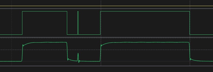
I put two more captures on the one drive, “Autel BMW X7.sal” and “ABC Good.sal”. The areas of importance I marked in the image below. The ABC Good capture has two instances of receiving the RF packets from the TPMS sensor. I think the larger ~25 ms “frame” is the preamble, the smaller ~5-6 ms “frames” are the sync bytes with the actual data.
The ABC Good is my hardware that I’m starting up and when I see the RF initialization, I triggered the TPMS sensor twice. That explains the two RF packets in the capture.
The Autel device seems to stop receiving packets after it gets the first one and processes it. It’s not collecting the two other packets from the TPMS sensor. From what I can tell, the TPMS sensor programmed for the BMW X7, sends the preamble once, then three packets of data. Looking at the data in URH, the data is the same for all three packets.
I was thinking I have two possible paths forward, 1) Continue using Logic 2, trying to get the “bits” out to a spreadsheet, haven’t quite figured that one out, or 2) Figure out how to collect the data via firmware on my device to get all the “bits”. Either way, once I get the “bits”, I’ll have to figure out how to decode them into something meaningful.
I feel this is a huge step forward, at least now that I can receive the same data that the Autel device is getting, I can at least work with it in code.
Again, thanks for all your help with this, greatly appreciated.
Yes, this is good progress. The hard part now is to reconcile how rtl_433 is decoding the pulses to get the hex data that you expect, vs. the pulses that you’re seeing on the GPO2 of the CC1101 chip.
As far as I can tell, the CC1101 is configured w/ the following settings:
FSK (Frequency Shift Key) demodulation (2-FSK)
~433.92 MHz base frequency
(assuming standard 26 MHz Xtal frequency)
200 kHz channel spacing
(set to channel 0, or ~433.92 MHz)
325 kHz channel bandwidth (RX filter)
GPO0 = carrier sense (RSSI above threshold on receive)
GPO2 = asynchronous serial output
So, I’d expect GPO0 to be high when enough signal detected at given frequency range (~433.92 MHz), and GPO2 to be high (1) when at the ‘higher’ frequency level / above ‘base frequency’ and low (0) when at the ‘lower’ frequency level / below ‘base frequency’ (i.e., 2-FSK demodulated asynchronous output).
However, when looking at your *.cu8 file captured from rtl_433, it doesn’t appear to decode a similar pulse pattern to what is seen on Saleae for GPO2. It may be that the rtl_433 is doing extra processing on the bitstream beyond the RF demodulated pulse, but I think this is the key to figuring out how to decode GPO2 into the hex data you expect.
no analog data needed, as long as glitch filter enabled and pulses look good
Without any analog capture data, you can capture more data / longer waveform and not worry as much about file size
(analog data at 50 MS/s uses up storage much faster than digital only )
… and then, trying to figure out how to align / match between the rtl_433 pulses and GPO2 pulses, so you can then decode the bitstream in the same way to get the desired hexidecimal output.