Hi,
Can someone tell me what the arrow signifies on the clock signal please?
Camerart
If you mean a little up or down arrow on a clock edge for a SPI or I2C bus, the arrow signifies the active edge - the point where the data value is sampled. For SPI the active edge can be configured in the analyzer’s setup. For I2C the active edge is fixed.
Hi P,
As mine shows the arrow on the wrong edge, but the signals look ok, does this mean that it is the analyser, that needs changing, and not a failt in my reading of the signals?
C
Which analyzer are you using? I2C looks like:

The SPI analyzer is configurable. The configuration dialog looks like:

and opens when you add a SPI analyzer. You can also open it using the Edit menu option in the popup menu you get clicking on the three vertical dots shown in the image below:
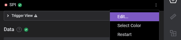
You need to hover the cursor over the SPI analyzer line for the dots to show up.
Note that the SPI clock settings are in terms of its inactive state (high or low) and leading or trailing edge.
If this doesn’t help you sort out the issue you should tell use which analyzer you are using and show us a screen capture of a portion of a capture.