Hi there.
I’m new to Saleae, so apologies in advance if this seems like a trivial question.
What does a small white dot, a small red dot, a large green dot, an orange square mean.
Like here, for example…
@smarty8 I’ll need to get this documented on your support site! It looks like the information there is outdated.
In the meantime, here is a quick summary, in order of them appearing in a single SMBus transaction, and a transaction can be made up of multiple smaller 8-bit words.
Green circle = Start condition for the entire transaction
Circle matching color of waveform = Stop bit for an 8-bit word (except the last one)
Red circle = Stop bit for the last 8-bit word
Orange square = Stop condition for the entire transaction
As another example for reference, here is an image below for an SMBus Write transaction that contains three 8-bit words.
Could you provide an exact link to an item in the FAQ or User Guide that explains this point. I spent two days crawling through the User Guide, but I could not find an explanation for the symbols mentioned above in the question.
And since you answered, I dare to ask one more question.
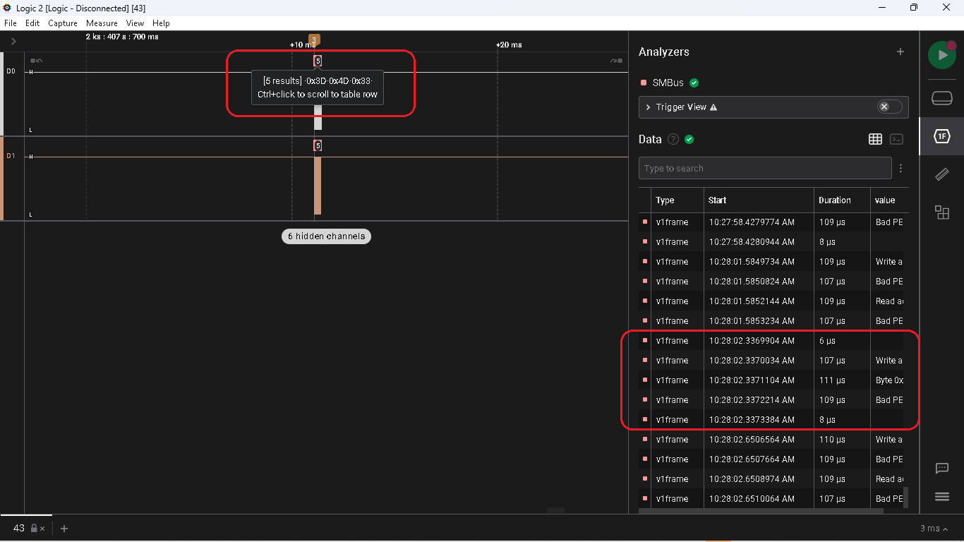
Why is the first byte (circled in red in the capture below) recognized as 3D?
Although it is obvious that the value of this byte is 01111010 (7A). Although the next byte is decoded correctly 01001101(4D)
What’s wrong with the first byte? And this is not the only event. So throughout the capture. I gues that this is also the reason for the constantly present PEC error.
TIA
@smarty8 The SMBus user guide can be found in the link below. I added descriptions for the symbols as well.
For your question about why the highlighted portion is read as 0x3D, the below support article may explain it:
Unfortunately however, our SMBus analyzer currently does not support extension add-ons in the same way our I2C analyzer does (due to the SMBus analyzer using an older frame format call Frame v1, which we haven’t updated for all of our analyzers yet — and HLAs are not compatible with this older frame format), so the workaround of adding the “I2C 8-bit address display” extension won’t work on the SMBus out of the box.
Well…
Returning to the question of the impossibility of correct decoding of the V1 Frame, this complicates the analysis, but in principle this is not critical. I know for sure that on the PCB of the SMBus laptop, address 7A is the address of the chip EMC2112 RPM-Based Linear Fan Controller with Hardware Thermal Shutdown by SMSC, which is logical in principle and makes further analysis possible.
But throughout the entire capture, sometimes there are sequences of events that I cannot unambiguously interpret.
Here is one of the snippets.
I made Timing Markers N3 and N5 for clarity on the chart, corresponding to the time in the Data Table 10:28:02.3369904 and 10:28:02.3373384, respectively.
@smarty8 Strange! I can’t quite explain what’s causing that. I was immediately able to reproduce the issue as well. I’ll get this on our backlog to review and we’ll follow up.
We found the root cause. The SMBus analyzer generates short, empty frames for the start and stop condition, so they show up in the data table. They are hidden from the graph because any frame that does not contain any text gets hidden by default.
I also wanted to add that it’s normal for the SDA line to go high briefly when the component driving the SDA line low switches between the master and the slave device. For example, when the master device finishes transmitting data, it will then release the SDA line, allowing the slave to pull it low to signal the ACK. There is sometimes a brief time during the switch where neither component is pulling the line low, which can produce short positive pulse. This is usually before or after a ACK/NAK bit.
Wow!
I’m glad the issue was resolved so quickly.
Maybe these are your explanations about the fact that not all events are displayed on the graph and the nuances of SMBus operation should be included in the User Guide so that inexperienced users like me do not waste your time?
Will this bug be fixed in the next update?
Mark, if you already responded, I would like to ask you a couple more questions.
I spent a few days crawling through the User Guide, but I could not find an explanation differences FrameV1 and FrameV2
Could you explain these differences in detail?
What prevents the analyzer from making it correctly interpret the first byte of the frame as a seven-bit address value?
Why does the analyzer interpret this address byte as an eight-bit value, even though all revisions of the SMBus specification from 1.0 to 3.1 (and the i2c specification from which SMBus is derived) unambiguously define the address byte as a seven-bit value, and the zero bit is used to indicate an R/W operation?
In none of the above documents, I found any mention of any situations when an address byte would be interpreted as an eight-bit value.
In any case, thank you all for your participation.
You’re right! Ideally, the empty frames for start and stop conditions should not be counted nor represented in the decoded protocol box above the waveform. Since this is a bug we will eventually solve, I don’t think it’s something I’d want to include in an SMBus user guide, though I may consider making note of that behavior if we might not be able to fix this anytime soon. Having said that, was there anything specific you wanted us to document in our SMBus user guide below?
As for the bug being fixed in the next update, and for the additional questions you had, our software team is currently quite swamped at the moment. I’ll let you know once we have updates on these topics.
For now, I can leave you with the support article below, which documents the FrameV2 formatting.
Hi, Tim.
Thx for your answer, but I don’t see a link to “article below”. If you mean the link aboveSMBus Analyzer - User Guide, then of course I read it, but there is not even a mention of FrameV.
I guess it would be appropriate to put Mark’s explanation there.